_WH_800x800px.webp "SL2690A-E High Precision Closed Loop Stepper Driver for CNC and Automation Systems")
_WH_800x800px.webp "SL2690A-E(6)_WH_800x800px")
_WH_800x800px.webp "SL2690A-E(2)_WH_800x800px")
_WH_800x800px.webp "SL2690A-E(4)_WH_800x800px")
_WH_800x800px.webp "digital closed loop stepper motor driver")
_WH_800x800px.webp "industrial closed-loop stepper driver")
_WH_800x800px-150x150.webp)
_WH_800x800px-150x150.webp)
_WH_800x800px-150x150.webp)
_WH_800x800px-150x150.webp)
_WH_800x800px-150x150.webp)
_WH_800x800px-150x150.webp)
Description
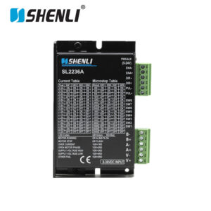
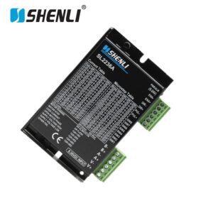
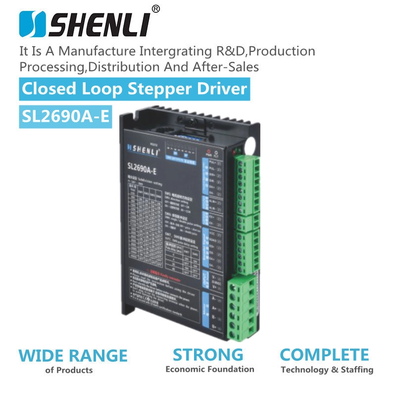
High Precision Closed Loop Stepper Driver with Encoder Feedback
The SL2690A-E closed-loop stepper driver is designed for high-accuracy motion control applications. It combines advanced digital control technology with real-time encoder feedback.
Unlike traditional open-loop stepper drivers, this closed-loop stepper driver continuously monitors motor position. It automatically corrects position errors during operation.
The driver provides stable performance for CNC machines, industrial automation equipment, robotics systems, and precision positioning applications.
With intelligent PID compensation and anti-step-loss technology, the SL2690A-E improves positioning reliability. It helps users achieve higher accuracy and smoother motion control.
Advanced Closed Loop Control Technology
The SL2690A-E uses a digital closed-loop control system. It receives real-time feedback from incremental encoders.
The encoder interface supports 1000 PPR to 5000 PPR resolution options. This allows precise monitoring of motor position and speed.
The built-in correction function automatically compensates for tracking errors. It reduces positioning deviation during high-speed operation.
The anti-step-loss function detects abnormal movement conditions. The driver can recover position automatically through configurable strategies.
This closed-loop design provides servo-like performance while maintaining the simplicity and cost advantages of stepper motor systems.
Stable Motion Performance for Industrial Applications
The SL2690A-E closed-loop stepper driver supports a maximum input frequency of 200 kHz. It provides fast response for demanding automation tasks.
The driver supports 1 to 64 microstep resolutions. Users can select suitable settings for different motion requirements.
Its optimized control algorithm reduces low-speed vibration. It also improves motor smoothness and running stability.
The speed stability can reach ±0.1 percent. This ensures consistent performance in precision equipment.
The dual H-bridge output design provides efficient motor control. It supports both 2-phase and 4-phase stepper motors.
Flexible Electrical Configuration
The SL2690A-E operates with a 24V DC power supply. A 36V DC version is also available for specific applications.
The adjustable output current ranges from 0.5A to 7.0A. This allows compatibility with different stepper motor sizes.
The driver uses standard 5V TTL Step and Direction signals. It works with most CNC controllers and automation systems.
The minimum pulse width is only 2 microseconds. This ensures reliable communication with high-speed control platforms.
Intelligent Protection and Alarm Functions
The SL2690A-E integrates multiple industrial protection features. These functions improve system reliability and operational safety.
Built-in protection includes:
- Over current protection with response time below 100 microseconds
- Over-temperature shutdown at 85°C
- Short circuit protection
- Encoder error detection
- Step loss monitoring
- Stall detection function
The RUN and ERROR LED indicators provide clear operating status information.
The alarm output supports open collector signals. Users can connect it easily with PLC systems.
Industrial Grade Design and Reliable Operation
The compact driver design measures approximately 70 × 55 × 25 mm. It supports wall mounting and optional DIN rail installation.
The signal and power interfaces feature an opto-isolation design. This improves electrical protection in industrial environments.
The EMC protection design reduces interference from surrounding equipment.
The SL2690A-E operates reliably from -10°C to 50°C. It supports 20% to 85% non-condensing humidity conditions.
The insulation resistance reaches ≥100 MΩ at 500V DC. This ensures long-term operational reliability.
Easy Integration with CNC and Automation Systems
The SL2690A-E closed-loop stepper driver supports multiple control modes.
a. It is compatible with Step/Dir and CW/CCW signals.
b. It works with PLC systems and PC-based motion controllers.
c. It can directly replace many traditional open-loop stepper solutions.
The driver supports various encoder brands. It also enables flexible position and speed mode switching.
This makes it an ideal upgrade solution for manufacturers seeking better accuracy without replacing existing stepper motors.
Wide Range of Applications
The SL2690A-E high-precision closed-loop stepper driver is suitable for:
- CNC machining equipment
- Automated assembly systems
- Industrial robotic modules
- Laser cutting machines
- Laser engraving equipment
- PCB routing and testing machines
- Precision positioning platforms
- Open-loop stepper system upgrades
It helps equipment manufacturers improve motion accuracy, reduce maintenance costs, and increase production reliability.
Performance indicators:
1. Electrical indicators |
||||
| instructions | SL2690A-E | |||
| Mini value | Typical values | Max. Value | Unit | |
| Output current(peak) | 2 | – | 6 | A |
| Voltage DC(AC) | 18 | 50 | 90 | V |
| Control signal current | 6 | 10 | 16 | mA |
| Step pulse frequency | 0 | – | 400 | KHz |
| Step pulse width | 2 | – | – | us |
| Directional signal width | 100 | – | – | us |
| Under-voltage protection point | – | 20 | – | VDC |
| Overvoltage protection point | – | 90 | – | VDC |
| Drive initialization time | 2 | – | – | s |
| Insulation resistance | 500 | MΩ | ||
| 2. Environmental indicators | ||||
| Cooling way | Natural cooling or forced air cooling | |||
| Using environment | occasion | Can not be placed next to other heating equipment, to avoid dust, oil, corrosive gas, humidity is too high and strong vibration place, no combustible gas and conductive dust; | ||
| Temperature | 0——+50℃ | |||
| humidity | 40—90%RH | |||
| vibration | 10~55Hz/0.15mm | |||
| Keep temperature | -20℃~65℃ | |||
| Weight | 0.3KG | |||
3. Port description |
||||
1) Control signal interface |
||||
| Name | Function | |||
| PUL+ | Pulse input signal: Pulse effective edge adjustable, the default pulse rising edge effective; The pulse width should be greater than 1.2μs to reliably respond to the pulse signal. Input voltage range: 5~24V.In dual-pulse mode: CW | |||
| PUL- | ||||
| DIR+ | Directional input signal: A high- or low-level signal is used for direction control. To ensure reliable motor commutation, timing must be correct. The direction signal must be set before the pulse signal. It should be established at least 5 microseconds in advance. The initial motor direction depends on winding connections. Motor windings determine the default rotation direction. The direction can be changed by swapping winding wires. For example, exchange A+ and A- connections. Input voltage range: 5~24V. In dual-pulse mode: CCW |
|||
| DIR- | ||||
| EN+ | Enable the control signal. This input signal enables or disables the drive output. When ENA is connected to a low level, the driver disables output. When the internal optocoupler is on, the driver also disables output. The driver cuts off current to each motor phase. The motor enters a free state. In this state, the motor does not hold position. The motor does not respond to step pulses. When this function is not needed, enable the signal terminal to hang. Input voltage range: 5~24V |
|||
| EN- | ||||
| ALM+ | Alarm error output, OC open emitter output, output maximum current 50mA, maximum withstand pull-up voltage 24V | |||
| ALM- | ||||
| EX+ | place output | |||
| EX+ | ||||
2) Power interface |
||||
| Power supply and motor power interface | ||||
| Interface name | Features | |||
| V+ | DC AC co-source, power supply voltage range: DC 20-90VDC/, AC 20-60VAC | |||
| V- | DC AC co-source, power supply voltage range: DC 20-90VDC/, AC 20-60VAC | |||
| A+ | Stepping motor A + phase winding interface | |||
| A- | Stepping motor A-phase winding interface | |||
| B+ | Stepping motor B + phase winding interface | |||
| B- | Stepping motor B-phase winding interface | |||
-300x300.jpg)
-300x300.jpg)