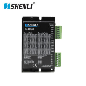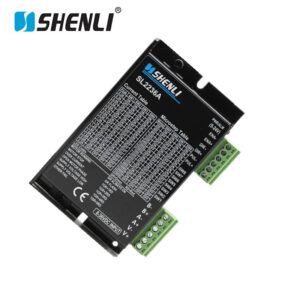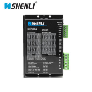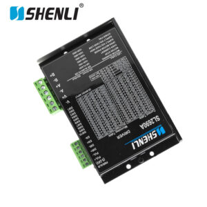
.jpg "SL28110A-E Closed Loop Stepper Driver")
.jpg "SL28110A-E(2)")
.jpg "SL28110A-E(3)")
.jpg "SL28110A-E(4)")
.jpg "SL28110A-E(6)")
.jpg "SL28110A-E Closed Loop Stepper Driver")
-150x150.jpg)
-150x150.jpg)
-150x150.jpg)
-150x150.jpg)
-150x150.jpg)
-150x150.jpg)
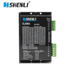
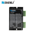
Description
SL28110A-E Closed Loop Stepper Driver is a next-generation motion control solution designed to deliver the precision of a stepper system with the reliability and feedback capabilities of servo technology. By integrating advanced closed-loop control algorithms with real-time encoder feedback, the SL28110A-E Closed Loop Stepper Driver effectively eliminates step loss, improves positioning accuracy, and significantly enhances the overall performance of automated machinery operating under dynamic load conditions.
Engineered for demanding industrial applications, the SL28110A-E Closed Loop Stepper Driver is widely used in CNC machinery, semiconductor manufacturing equipment, laser cutting systems, automated assembly lines, packaging machines, textile equipment, inspection systems, and precision positioning platforms. Unlike traditional open-loop drivers, this advanced Closed Loop Stepper Driver continuously monitors motor position and automatically compensates for load variations, ensuring accurate and reliable motion even during rapid acceleration and deceleration.
SL28110A-E Closed Loop Stepper Driver – Technical Specifications
General Information
- Product Model: SL28110A-E Closed Loop Stepper Driver
- Driver Technology: DSP-Based Digital Closed-Loop Control
- Motor Compatibility: 2-Phase Closed-Loop Hybrid Stepper Motors
- Feedback Device Support: Incremental Encoder Feedback
- Control Architecture: Position Closed-Loop with Real-Time Error Compensation
Electrical Specifications
- Input Voltage Range: AC 60V – 110V or DC 80V – 160V
- Recommended Operating Voltage: AC 80V – 100V
- Output Current Range: 2.8A – 11.0A Peak Adjustable
- Current Adjustment: Software and DIP-Switch Selectable
- Logic Signal Voltage: 5V / 12V / 24V Compatible
- Pulse Input Frequency: Up to 500 kHz
Motion Control Features
- Command Modes: Pulse & Direction (PUL/DIR), CW/CCW
- Position Correction: Automatic Following Error Compensation
- Step-Loss Detection: Integrated Closed-Loop Monitoring
- Auto-Tuning Function: Intelligent Parameter Optimization
- Microstep Resolutions: Programmable Electronic Subdivision
- Speed Regulation: Dynamic Torque Adjustment Throughout the Speed Range
- Acceleration Capability: Optimized for High-Speed Start/Stop Applications
Protection Functions
- Encoder Disconnection Alarm
- Motor Overload Protection
- Over-Current Monitoring
- Over-Voltage Protection
- Under-Voltage Detection
- Over-Temperature Shutdown
- Position Tracking Error Alarm
- Phase Fault Protection
Mechanical & Installation Data
- Cooling Method: Forced-Air Assisted Aluminum Heat Sink Design
- Mounting Configuration: Standard Industrial Panel Mount
- Housing Material: Industrial-Grade Metal Enclosure
- Status Indicators: Power, Alarm, Pulse, Direction, Encoder Feedback LEDs
Environmental Specifications
- Operating Temperature: 0°C to +50°C
- Storage Temperature: -20°C to +80°C
- Humidity: <90% RH, Non-Condensing
- Protection Class: IP20
- EMC Performance: Industrial Anti-Interference Design
Reliability Characteristics
- Control Response Time: <1 ms
- Continuous Duty Operation: Suitable for 24/7 Industrial Applications
- Expected Service Life: ≥50,000 Hours
- Noise Reduction Technology: Advanced Resonance Suppression Algorithm
- Positioning Accuracy Improvement: Up to 100% Step-Loss Elimination Compared with Open-Loop Systems
Typical Applications
- CNC Machining Centers
- Laser Cutting and Engraving Equipment
- Semiconductor Manufacturing Systems
- Automated Assembly Machinery
- Packaging and Labeling Equipment
- Industrial Robotics and Gantry Systems
- Precision Inspection Platforms
- Electronic Production Lines
- High-Speed Pick-and-Place Machines
- Automated Material Handling Systems
Performance indicators |
||||
1. Electrical indicators |
||||
| Cooling way | Natural cooling or forced air cooling | |||
| Using the environment | occasion | Can not be placed next to other heating equipment to avoid dust, oil, corrosive gas, ,high humidity and strong vibration place, no combustible gas and conductive dust; | ||
| Temperature | 0——+50℃ | |||
| humidity | 40—90%RH | |||
| vibration | 10~55Hz/0.15mm | |||
| Keep temperature | -20℃~65℃ | |||
| Weight | 0.2KG | |||
2. Environmental indicators |
||||
| instructions | SL28110A-E | |||
| Mini value | Typical values | Max. Value | Unit | |
| Output current(peak) | 2 | – | 6 | A |
| Voltage DC(AC) | 18 | 70 | 110 | V |
| Control signal current | 6 | 10 | 16 | mA |
| Step pulse frequency | 0 | – | 400 | KHz |
| Step pulse width | 2 | – | – | us |
| Directional signal width | 100 | – | – | us |
| Undervoltage protection point | – | 22 | – | VDC |
| Overvoltage protection point | – | 120 | – | VDC |
| Drive initialization time | 2 | – | – | s |
| Insulation resistance | 500 | MΩ | ||
Ports and wiring |
||||
1. Port description |
||||
1) Control signal interface |
||||
| Name | Function | |||
| PUL+ | Pulse input signal: Pulse effective edge adjustable, the default pulse rising edge effective; The pulse width should be greater than 1.2μs in order to reliably respond to the pulse signal. Input voltage range: 5~24V.In dual-pulse mode: CW | |||
| PUL- | ||||
| DIR+ | Directional input signal:High/low level signal, in order to ensure reliable commutation of the motor, the direction signal should be established at least 5μs before the pulse signal. The initial running direction of the motor is related to the wiring of the motor windings, and the initial running direction of the motor can be changed by exchanging any of the windings (such as A+, A- exchange). Input voltage range: 5~24V. In dual-pulse mode: CCW | |||
| DIR- | ||||
| EN+ | Enable control signal. This input signal is used to enable or disable drive output. When ENA is connected to low level (or the internal optocoupler is on), the driver will cut off the current of each phase of the motor and the motor is in a free state and does not respond to the stepping pulse.When this function is not needed, enable the signal terminal to hang. Input voltage range: 5~24V | |||
| EN- | ||||
| ALM+ | Alarm error output, OC open emitter output, output maximum current 50mA, maximum withstand pull-up voltage 24V | |||
| ALM- | ||||
| EX+ | In place output | |||
| EX+ | ||||
2)Power interface |
||||
| Power supply and motor power interface | ||||
| Interface name | Features | |||
| AC+ | Dc AC common source, power supply voltage range: DC 18-110VDC/, AC 18-80VAC | |||
| AC- | Dc AC common source, power supply voltage range: DC 18-110VDC/, AC 18-80VAC | |||
| A+ | Stepping motor A + phase winding interface | |||
| A- | Stepping motor A-phase winding interface | |||
| B+ | Stepping motor B + phase winding interface | |||
| B- | Stepping motor B-phase winding interface | |||
_WH_800x800px-300x300.webp)
_WH_800x800px-300x300.webp)