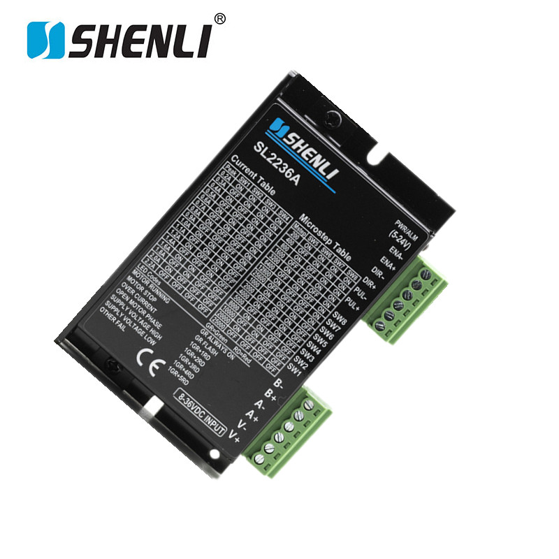
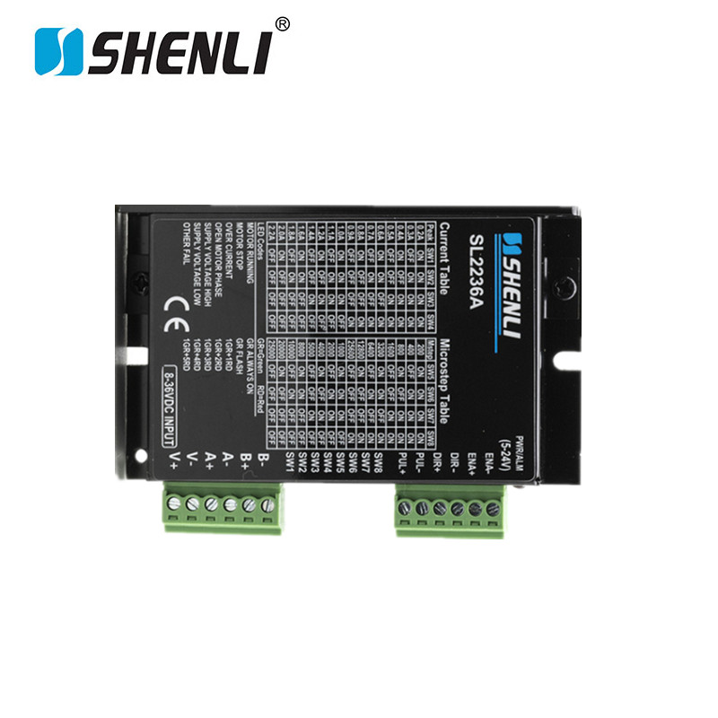
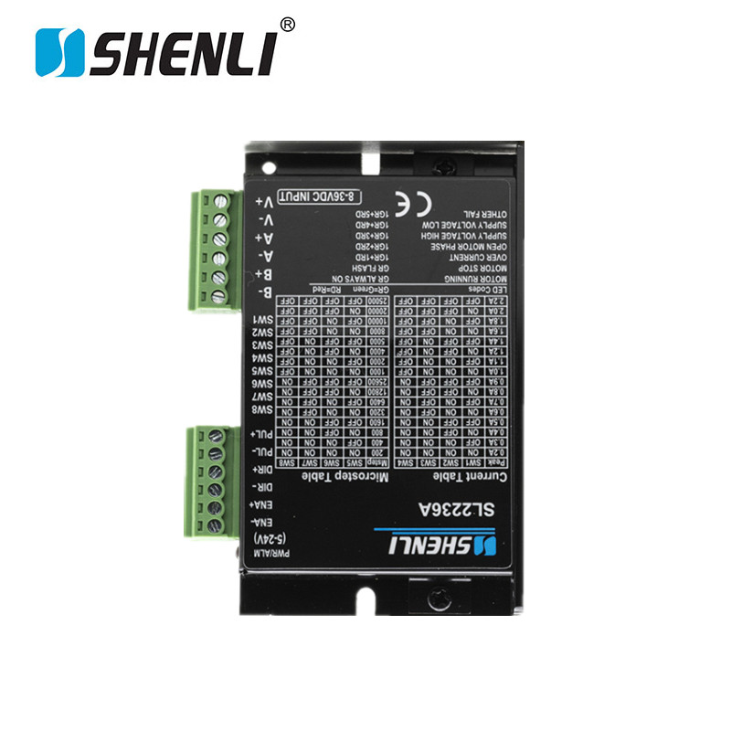
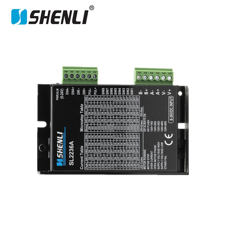
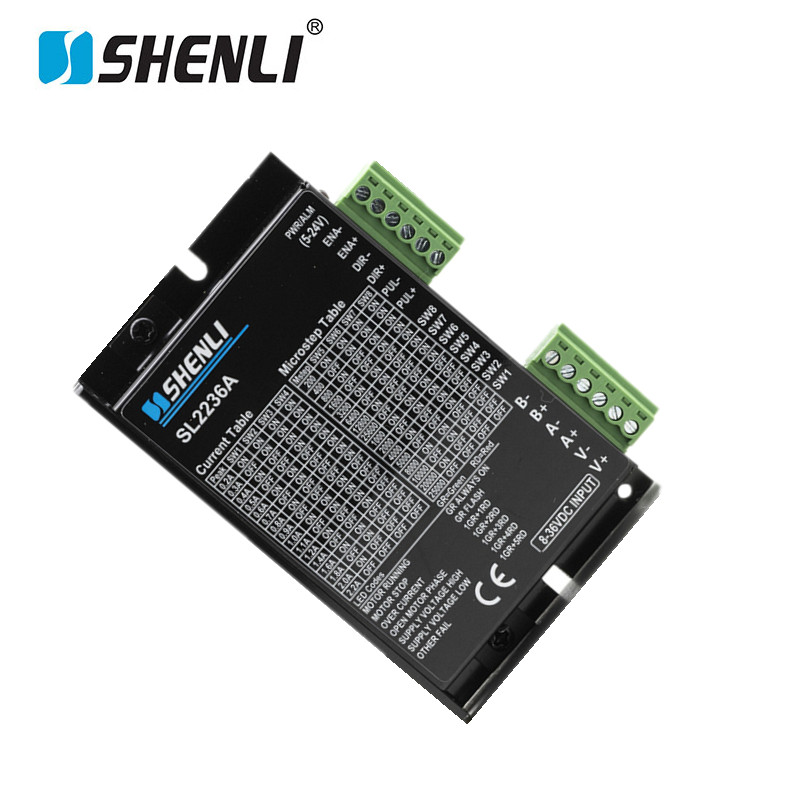
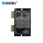
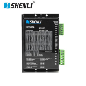
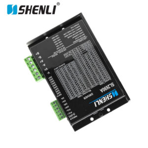
SL2236A Stepper Driver for Automation Equipment

SL2236A Stepper Driver is a compact high-performance digital stepper motor driver engineered for smooth motion control, optimized current regulation, and dependable operation in automation equipment, CNC systems, positioning devices, and intelligent manufacturing applications.


Description

 SL2236A Stepper Driver is a high-performance digital motor controller engineered to deliver smooth, accurate, and reliable motion control for a wide range of industrial automation applications. Designed to work seamlessly with 2-phase stepper motors, the SL2236A Stepper Driver provides precise current regulation, advanced microstepping technology, and stable pulse processing, making it an ideal solution for CNC machinery, laser equipment, automated assembly systems, packaging machines, textile equipment, and precision positioning devices.

As industrial automation continues to demand higher efficiency and greater positioning accuracy, the SL2236A Stepper Driver offers an excellent balance between performance, reliability, and cost-effectiveness. By optimizing motor operation and reducing resonance, it helps improve machine productivity while extending motor service life.

Precise Control and Smooth Motor Performance

One of the key advantages of the SL2236A Stepper Driver is its advanced digital control algorithm. Unlike conventional analog drivers, this driver continuously adjusts motor current to achieve smoother motion, lower vibration, and reduced acoustic noise. As a result, machines operate more quietly while maintaining exceptional positioning accuracy.

Furthermore, the driver supports multiple microstep resolutions, allowing users to fine-tune motion performance according to specific application requirements. Whether used in a precision CNC router, automated inspection system, or laboratory equipment, the SL2236A Stepper Driver delivers stable torque output and accurate speed control throughout the operating range.

Designed for Industrial Reliability

Reliability is critical in automation environments. Therefore, the SL2236A Stepper Driver incorporates multiple protection functions, including over-voltage protection, over-current protection, short-circuit protection, and overheating protection. These intelligent safeguards help prevent unexpected downtime and protect both the driver and motor from damage.

In addition, the compact housing design allows easy integration into electrical control cabinets and automation equipment. The driver maintains stable performance even during continuous operation, making it suitable for demanding industrial production lines and long-duty-cycle applications.

Precision Manufacturing and Quality Assurance

Every SL2236A Stepper Driver is manufactured using high-quality electronic components and advanced SMT production technology. Precision circuit assembly, strict quality control procedures, and comprehensive functional testing ensure consistent performance and long-term durability.

Before shipment, each unit undergoes electrical verification, load simulation testing, thermal stability evaluation, and operational inspections. This rigorous manufacturing process guarantees dependable performance in real-world industrial environments.

Ideal Applications

The SL2236A Stepper Driver is widely used in:

  • CNC engraving and milling machines
  • Laser cutting and marking equipment
  • Automated packaging systems
  • Semiconductor manufacturing equipment
  • Textile machinery
  • Electronic assembly lines
  • Pick-and-place systems
  • Precision positioning platforms
  • Industrial robotics
  • Laboratory automation devices

With its advanced digital architecture, excellent motion accuracy, and industrial-grade reliability, the SL2236A Stepper Driver provides a dependable motion-control solution for modern automation systems that require precise positioning, smooth operation, and long-term performance.

Perormance index:
1.electric index:
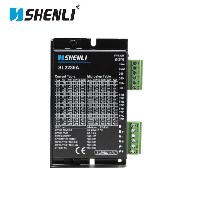
Explain SL2236A SL2236A Subdivide Setting list
min value Typical value Max value Unit Subdivide No. 1 2 4 8 16 32 64 128
Output current (peak value) 0.2 2.2 A
Supply Voltage 8 24 36 VDC D2 ON ON OFF OFF ON ON OFF OFF
control signal current 6 10 16 mA D1 ON OFF ON OFF ON OFF ON OFF
Stepping pulse frequency 0 300 KHz
Stepping pulse width 2 us Indicator light pin function description
Direction signal width 100 us Mark symbol Function Annotation
Under voltage protection point 7.5 VDC PWR Power light When the power is on, the indicator light is on
Over voltage protection point 42 VDC Im Motor coil current setting potentiometer Adjust the motor phase current, counter clockwise reduce and clockwise  increase
Drive initialization time 2 s + Input signal optoelectronic isolation positive end Connect signal power supply, +5 V,~+24V can be driven
Insulation resistance 500 PU Stepping pulse signal The falling edge is effective. Whenever the pulse changes from high to low, the motor takes a step and the pulse width is required>2.5us
2.Environmental index DR Direction control signal Used to change motor steering
Type of cooling Natural cooling or forced air cooling MF Motor release signal When effective (low level), turn off the motor coil current and the motor is in free state
Environmental conditions Occasion Can’t be put it next to other hot equipment,avoid dust, oil, corrosive gas, humidity and strong vibration places,no combustible gas and conductive dust V+ Power supply positive electrode DC6~30v,Direct current input,Power >100W
V- Power supply negative electrode
Temperature 0~+50°C A+,A- Motor connect Electrical wiring B-,B+ ——M——A+,A-
Humidity 40~90%RH B+,B-
Vibration 10~55Hz/0.15mm
Storage temperature (-20°C~65°C) Remark: 1,Do not connect the power in reverse,Input voltage not to above DC36V.
Weight 180g                  2,The green indicator PWR will on when the driver is powered on
COM port and connection:
Name Function
PUL+(CCW+) Pulse input signal: The pulse effective edge is adjustable,default pulse rising edge is valid; In order to reliably respond to the pulse signal , the pulse width should be greater than 1.2µs.Input voltage range:3.3~28V.  Double pluse mode(under) : CCW
PUL-(CCW-)
DIR+(CW+) Direction input signal:High/low electrical level signal, in order to ensure reliable motor reversing, the direction signal should be established at least 5µs before the pulse signal.The initial running direction of the motor is related to the wiring of the motor windings. The direction of the initial running of the motor can be changed by interchanging any one-phase winding (such as A+ and A- exchange). Double pluse mode(under) : CW
DIR-(CW-)
ENA+(ALM+) Enable control signals:this input signal is used to enable or disable drive output.ENA connected to the low level (or internal optocoupler turns on), the driver will cut off the each phase of the motor current, make the motor in a free state and can’t be respond to the stepping pulse.When this function is no needed, suspended the enable signal terminal is OK.Input voltage range :3.3~28V. Can be according the customer’s requirements to set as a alarm output terminal or running speed adjusted output terminal
ENA-(ALM-)
GND Direct current source
VDC Direct current power positive,Range :+8~+36V,recommend +24V
A+,A- A phase of winding motor
B+,B- B phase of winding motor